Monday, February 8, 2010

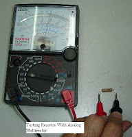
Resistor Measurement


Instructions
Step 1:
Set the multimeter dial to the unit you want to measure. Voltage is marked by a V, amperage by an A and resistance by an Ω, called an omega.

Step 2:
Set the dial to the maximum value you want to measure. Usually, the values differ from each other by a factor of 10. For example, 10 ohms, 100 ohms and 1k ohms for resistance. The letter k stands for kilo meaning thousand. The letter m stands for milli, meaning thousandth. If you do not know what value to use, use the very highest to minimize the risk of damaging your multimeter.

Step 3:
If you are measuring resistance, turn the circuit off and unplug it. Otherwise, power it on.

Step 4:
Touch the probes to the two points you wish to measure the difference between. If you are measuring the resistance of a particular resistor, for example, put one on either side of the resistor. If you are measuring amperage, put the red lead on the positive side and the black one on the negative side of the circuit component you are measuring.

Step 5:
Look at the value on the dial or digital display. If you are using a digital multimeter, it will tell you in exactly the right unit. For example, it will say 10 V if there is a 10 volt drop over the component. With analog multimeters, you read the dial as a value out of 10. If you had it set to 1 volt and the dial read a 5, it would mean 0.5 volts. If it were set to 100 millivolts and the dial read 5, however, it would mean 50 millivolts.

Step 6:
Change the setting if necessary. If the ohmeter registers a value that is less than 1/10th of the total, you should set it down one level lower. For example, if you have it set to 100 Ω and it reads below 10 Ω, you should set it to 10 Ω to get a more precise value.

Using Analog Multimeter


Multimeters are very easy to use, and they are the most essential piece of test equipment that is needed if any electronics construction work is to be undertaken. Fortunately the multimeter instructions of how to use them are straightforward, and they should give many years of good service is treated well. Additionally it is possible to use a multimeter to perform many types of test. Even the older analogue meters can be used in a variety of ways, and digital multimeters often have many measurement capabilities beyond the basic amps volts and ohms measurements.


When using the meter it is possible to follow a number of simple steps:

Insert the probes into the correct connections - this is required because there may be a number of different connections that can be used. Be sure to get the right connections, and not put them into the ones for a low current measurement if a high voltage measurement is to be made - this could damage the multimeter.


Set switch to the correct measurement type and range for the measurement to be made. When selecting the range, ensure that the maximum for the particular range chosen is above that anticipated. The range on the multimeter can be reduced later if necessary. However by selecting a range that is too high, it prevents the meter being overloaded and any possible damage to the movement of the meter itself.


Optimise the range for the best reading. If possible adjust it so that the maximum deflection of the meter can be gained. In this way the most accurate reading will be gained.


Once the reading is complete, it is a wise precaution to place the probes into the voltage measurement sockets and turn the range to maximum voltage position. In this way if the meter is accidentally connected without thought for the range to be used, there is little chance of damage to the meter. This may not be true if it left set for a current reading, and the meter is accidentally connected across a high voltage point!

Analog multimeter


An analogue meter moves a needle along a scale. Switched range analogue multimeters are very cheap but are difficult for beginners to read accurately, especially on resistance scales. The meter movement is delicate and dropping the meter is likely to damage it!

Each type of meter has its advantages. Used as a voltmeter, a digital meter is usually better because its resistance is much higher, 1 M or 10 M, compared to 200k for a analogue multimeter on a similar range. On the other hand, it is easier to follow a slowly changing voltage by watching the needle on an anlaogue display.

Used as an ammeter, an analogue multimeter has a very low resistance and is very sensitive, with scales down to 50 礎. More expensive digital multimeters can equal or better this performance.

Most modern multimeters are digital and traditional analogue types are destined to become obsolete.

Digital Multimeter (Part 2)


You are not at all likely to use the AC ranges, indicated by V~, on your multimeter.

An alternative style of multimeter is the autoranging multimeter:

The central knob has fewer positions and all you need to do is to switch it to the quantity you want to measure. Once switched to V, the meter automatically adjusts its range to give a meaningful reading, and the display includes the unit of measurement, V or mV. This type of meter is more expensive, but obviously much easier to use.

Where are the two meter probes connected? The black lead is always connected into the socket marked COM, short for COMMON. The red lead is connected into the socket labelled VmA. The 10A socket is very rarely used.

Digital Multimeter (Part 1)


Even digital multimeter are easy to use but still, some of the students confuse on handling it.

Multimeters are designed and mass produced for electronics engineers. Even the simplest and cheapest types may include features which you are not likely to use. Digital meters give an output in numbers, usually on a liquid crystal display.

The diagram shows a switched range multimeter:

The central knob has lots of positions and you must choose which one is appropriate for the measurement you want to make. If the meter is switched to 20 V DC, for example, then 20 V is the maximum voltage which can be measured, This is sometimes called 20 V fsd, where fsd is short for full scale deflection.

For circuits with power supplies of up to 20 V, which includes all the circuits you are likely to build, the 20 V DC voltage range is the most useful. DC ranges are indicated by on the meter. Sometimes, you will want to measure smaller voltages, and in this case, the 2 V or 200 mV ranges are used.

What does DC mean? DC means direct current. In any circuit which operates from a steady voltage source, such as a battery, current flow is always in the same direction. Every constructional project descirbed in Design Electronics works in this way.

AC means alternating current. In an electric lamp connected to the domestic mains electricity, current flows first one way, then the other. That is, the current reverses, or alternates, in direction. With UK mains, the current reverses 50 times per second.

Ohm's Law


In electrical circuits, Ohm's law states that the current through a conductor between two points is directly proportional to the potential difference or voltage across the two points, and inversely proportional to the resistance between them [provided that the temperature remains constant].

The mathematical equation that describes this relationship is:


where V is the potential difference measured across the resistance in units of volts; I is the current through the resistance in units of amperes and R is the resistance of the conductor in units of ohms. More specifically, Ohm's law states that the R in this relation is constant, independent of the current.

The law was named after the German physicist Georg Ohm, who, in a treatise published in 1827, described measurements of applied voltage and current through simple electrical circuits containing various lengths of wire.

BS 1852?

BS 1852 Coding for resistor values
BS 1852(British Standard 1852). The letter R is used for Ohms and K for Kohms M for Megohms and placed where the decimal point would go.

At the end is a letter that represents tolerance Where M=20%, K=10%, J=5%, G=2%, and F=1% D=.5% C=.25 B=.1%


BS 1852 coding examples
R33 0.33 ohms
2R2 2.2 ohms
470R 470 Ohms
1K2 1.2K ohms
22K 22K ohms
22K2 22.2K ohms
4M7 4.7M ohms
5K6G 5.6K ohms 2%
33KK 33k Ohms 10%
47K3F 47.3 K Ohms 1%

Resistor Colour Code


From my observation, most of the students quite difficult to remeber the caolur code of the resistor. Since the resistor is one of basic components to resist the current, i ask my students to make their own mnemonic on colour code just like

"Bad Boys Ravish Only Young Girls But Violet Gives Willingly"

How To Read The Code:

Resistor values are always coded in ohms, capacitors in picofarads (pF), and inductors in microhenries (µH).

band A is first significant figure of component value
band B is the second significant figure
band C is the decimal multiplier
band D if present, indicates tolerance of value in percent (no color means 20%)
For example, a resistor with bands of yellow, violet, red, and gold will have first digit 4 (yellow in table below), second digit 7 (violet), followed by 2 (red) zeros: 4,700 ohms. Gold signifies that the tolerance is ±5%, so the real resistance could lie anywhere between 4,465 and 4,935 ohms.

Basic Components in Electronic


An electronic component is a basic electronic element usually packaged in a discrete form with two or more connecting leads or metallic pads. Components are intended to be connected together, usually by soldering to a printed circuit board, to create an electronic circuit with a particular function (for example an amplifier, radio receiver, or oscillator). Components may be packaged singly (resistor, capacitor, transistor, diode etc.) or in more or less complex groups as integrated circuits (operational amplifier, resistor array, logic gate etc.)